
Why Choose a Plastic Blind Drain for Your Project?

Water that collects behind a retaining wall, beneath a landscaped area, or beside a paved path can weaken ground and create ongoing maintenance problems. A Plastic blind drain offers a practical way to collect and redirect subsurface water through a concealed drainage route. Its perforated structure allows water to enter while surrounding soil is kept out by a suitable filter layer. In the field, details matter: a drain placed beside compacted backfill may perform differently from one installed in loose, silty soil.

The right choice depends on site conditions, not just the product name. Consider expected water flow, soil type, installation depth, outlet location, and the load above the drain. Check the manufacturer’s specifications, and confirm that the filter fabric suits the soil; an unsuitable wrap can clog over time. A dependable outlet is essential. Without one, collected water has nowhere useful to go.

Plastic systems are often light to handle and resistant to corrosion, which can simplify transport and installation. Still, they are not a cure-all. Poor grading, crushed sections, or careless backfilling can reduce performance. Small mistakes matter. Before choosing a system, compare its capacity and dimensions with the project plan, and seek qualified drainage advice when site conditions are uncertain. This guide explores where a plastic blind drain can be useful, what to assess before installation, and which limitations deserve a closer look. A little caution now can prevent a wet surprise later.
Why Choose a Plastic Blind Drain for Your Project?

What a Plastic Blind Drain Is: Core, Filter Geotextile, and Flow Path

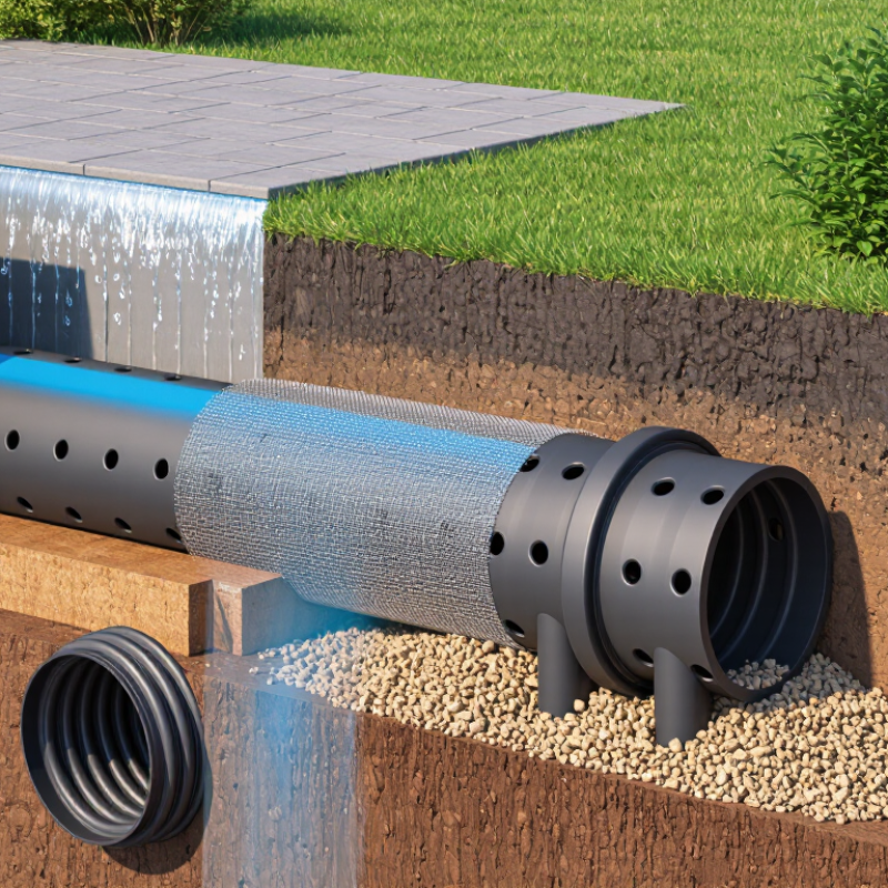
A plastic blind drain is a buried drainage unit with three working parts: a permeable geotextile, a hollow plastic core, and a route for water to discharge. The fabric faces the surrounding soil. It screens out particles while allowing water through; the core provides a low-resistance path along the drain. Not merely a wrap. If soil clogs the fabric, water entry slows. If the core is crushed or poorly connected, collected water has nowhere useful to go.

The Federal Highway Administration’s Geosynthetic Design and Construction Guidelines (NHI-07-092, 2008) treats filtration and drainage as separate design checks. It identifies apparent opening size and permittivity as key geotextile properties. ASTM D4751 measures opening size; ASTM D4491 measures permittivity. These test results help match a fabric to the soil and expected flow, rather than choosing by appearance alone. In practice, check the soil gradation, groundwater level, and outlet elevation before installation. A small gravel trench may look simple, but fine silt can change the design. That assumption is easy to make—and sometimes wrong. Keep the core’s flow path continuous, protect the fabric from tears during backfilling, and confirm the outlet remains clear after grading.

Which Site Data Guide Drain Placement: Soil, Groundwater, and Hydraulic Gradient

Why Choose a Plastic Blind Drain for Your Project?

Which Site Data Guide Drain Placement: Soil, Groundwater, and Hydraulic Gradient

A plastic blind drain can help move collected water away from a wet area, but placement should follow site evidence, not guesswork. Start with soil texture and infiltration observations. Clay-rich soil may hold water around a trench, while coarse sand can drain quickly but allow fine particles to migrate. A simple test pit can reveal layered soils, though one pit may not represent the whole site.

That estimate may be wrong.

Check groundwater levels at different times, especially after heavy rain or seasonal snowmelt. A single dry-weather reading can miss the highest water table. Survey ground and outlet elevations to establish the hydraulic gradient: water needs a continuous downhill route, without low spots that trap sediment. Confirm the drain assembly’s flow path, filter fabric, and aggregate requirements before setting trench depth. Poor outlet conditions can undermine an otherwise well-placed drain.

Tips: Mark utility lines, record elevations, and inspect the proposed outlet. If groundwater is near the trench base, seek a site-specific drainage assessment before excavation. Don’t assume.

How ASTM D4716 Measures In-Plane Flow Capacity Under Load

Why Choose a Plastic Blind Drain for Your Project?
How ASTM D4716 Measures In-Plane Flow Capacity Under Load

A plastic blind drain gives water a defined path through its core while the surrounding soil presses against it. But a high flow figure alone does not prove that the drain will perform well in a project. The test conditions matter.

ASTM D4716 measures water flow within a geosynthetic, parallel to its plane, under a specified compressive load and hydraulic gradient. In a typical test, a specimen sits between boundaries, water passes through it, and the flow rate per unit width is recorded. The applied load simulates pressure from soil or other materials. The result helps engineers compare products under stated conditions. It is not a universal field-flow guarantee.

When reviewing data, check the normal stress, gradient, specimen thickness, and test duration. These details shape the result. A drain tested at a light load may not retain the same capacity beneath deep fill. That matters. Also consider long-term compression, filter fabric, soil compatibility, and possible clogging. ASTM D4716 provides a useful measure, but it cannot recreate every site condition. I would treat the reported capacity as one design input, then ask whether the test setup resembles the project’s actual pressures and drainage path. A small mismatch can change the decision.

Why Choose a Plastic Blind Drain for Your Project? — How ASTM D4716 Measures In-Plane Flow Capacity Under Load

Item Definition or value Why it matters for a plastic blind drain
Test method ASTM D4716/D4716M: in-plane flow rate per unit width and hydraulic transmissivity of a geosynthetic under a constant head. Provides a standardized way to assess water flow within a drainage product’s plane while it is subjected to specified test conditions.
In-plane flow Water moving parallel to the plane of the geosynthetic, rather than through its thickness. This is the drainage direction used by a blind drain to collect and convey water toward an outlet.
Normal compressive stress Pressure applied perpendicular to the specimen during testing; the selected stress is a test condition, not a single universal value. A useful evaluation checks flow under stresses representative of the project, because compression can reduce drainage channels.
Hydraulic gradient, i The hydraulic head loss divided by the flow length; it is dimensionless. Flow results should be compared at stated gradients, since the driving head affects measured flow.
Flow rate per unit width, q q = Q/W, where Q is measured flow rate and W is specimen width. SI units: m²/s. Normalizing by specimen width supports comparison between test specimens of different widths.
Hydraulic transmissivity, θ θ = q/i for the reported test conditions. SI units: m²/s. Expresses the in-plane flow capacity relative to the hydraulic gradient; it is condition-dependent and should be reported with the test conditions.
Unit conversion 1 L/min per m of width = 1.667 × 10⁻⁵ m²/s. Helps convert commonly used flow-per-width units to SI units for consistent reporting.
Calculation example If Q = 0.60 L/min through a 0.30 m-wide specimen, then q = 2.0 L/min per m = 3.33 × 10⁻⁵ m²/s. At i = 0.10, θ = 3.33 × 10⁻⁴ m²/s. Illustrates the calculations only. These values are not product test results or a performance claim.
Project comparison Compare reported flow or transmissivity at matching normal stress, hydraulic gradient, and other stated test conditions. A higher result under comparable conditions can indicate greater measured in-plane flow capacity, but it does not by itself establish long-term field performance.

Note: ASTM D4716 results describe performance under the specified laboratory conditions. For design, review the complete test report and assess site-specific load, drainage length, hydraulic conditions, installation, and long-term behavior.

How ASTM D4491 Permittivity Data Informs Geotextile Filter Selection

A plastic blind drain relies on its geotextile wrap to admit water while limiting soil movement into the drainage core. ASTM D4491 measures geotextile permittivity: the rate of water flow through a fabric under a specified head, relative to its thickness. The result is typically reported in inverse seconds. It offers a useful comparison, but it is not a direct measure of how a drain will perform in every soil.

A higher permittivity may indicate greater capacity for flow across the fabric. Still, soil gradation, hydraulic pressure, and the risk of clogging matter too. A high number can look reassuring. I would not choose a filter by that figure alone. Check the test report, fabric construction, and the soil’s particle-size distribution together. On a site with fine, silty soil, for example, a geotextile that passes water readily may still be poorly matched if particles accumulate at its surface.

ASTM D4491 data helps narrow options, not replace project-specific judgment. Compare values tested using the same method and review the manufacturer’s reported test conditions. Then consider installation: folds, punctures, or crushed drain cores can restrict flow regardless of the laboratory result. It is easy to treat one number as certainty. It isn’t. A qualified geotechnical professional can assess whether the proposed filter suits the soil and expected water conditions.

How Outlet Design, Installation, and Clogging Checks Protect Drain Performance

A plastic blind drain works only when water has a clear route out. Its outlet deserves as much attention as the buried pipe. Choose an exit point that remains above standing water and can discharge safely away from foundations or slopes. A steady fall helps water move by gravity, but the required gradient depends on site conditions and the drainage layout. Avoid sharp bends and crushed sections near the outlet. Small details matter.

During installation, keep the pipe aligned and support it evenly with suitable drainage aggregate. Wrap or surround it with a compatible filter layer where soil could migrate into the openings. Check that the outlet is visible and accessible before covering the trench. It is easy to rush this step. I would also photograph the pipe route and outlet location; later, those details can save time when digging or inspecting.

Clogging checks should be simple and regular, especially after heavy rain or nearby soil work. Look for reduced flow, muddy discharge, standing water, or debris at the outlet. A clean outlet does not prove the full drain is clear, so compare its flow with previous checks. If water backs up, inspect accessible points before flushing or digging; forceful cleaning may damage plastic pipe or its filter. Small maintenance records help reveal changes early.

Why Choose a Plastic Blind Drain for Your Project?

How outlet design, installation, and clogging checks protect drain performance

Larger outlets can pass more water in this idealized comparison, but actual drainage depends on the full system. Keep the outlet unobstructed, install the drain to the specified grade, and check for sediment or debris regularly. Values are theoretical estimates using the orifice equation with a 0.6 discharge coefficient and 50 mm water head; they are not field-test results.